Tiny Tapeout > Tiny Tapeout Chips > Tiny Tapeout 2 > 94 Scalable synchronous 4-bit tri-directional loadable counter
94 Scalable synchronous 4-bit tri-directional loadable counter
94 : Scalable synchronous 4-bit tri-directional loadable counter
- Author: Steven Bos
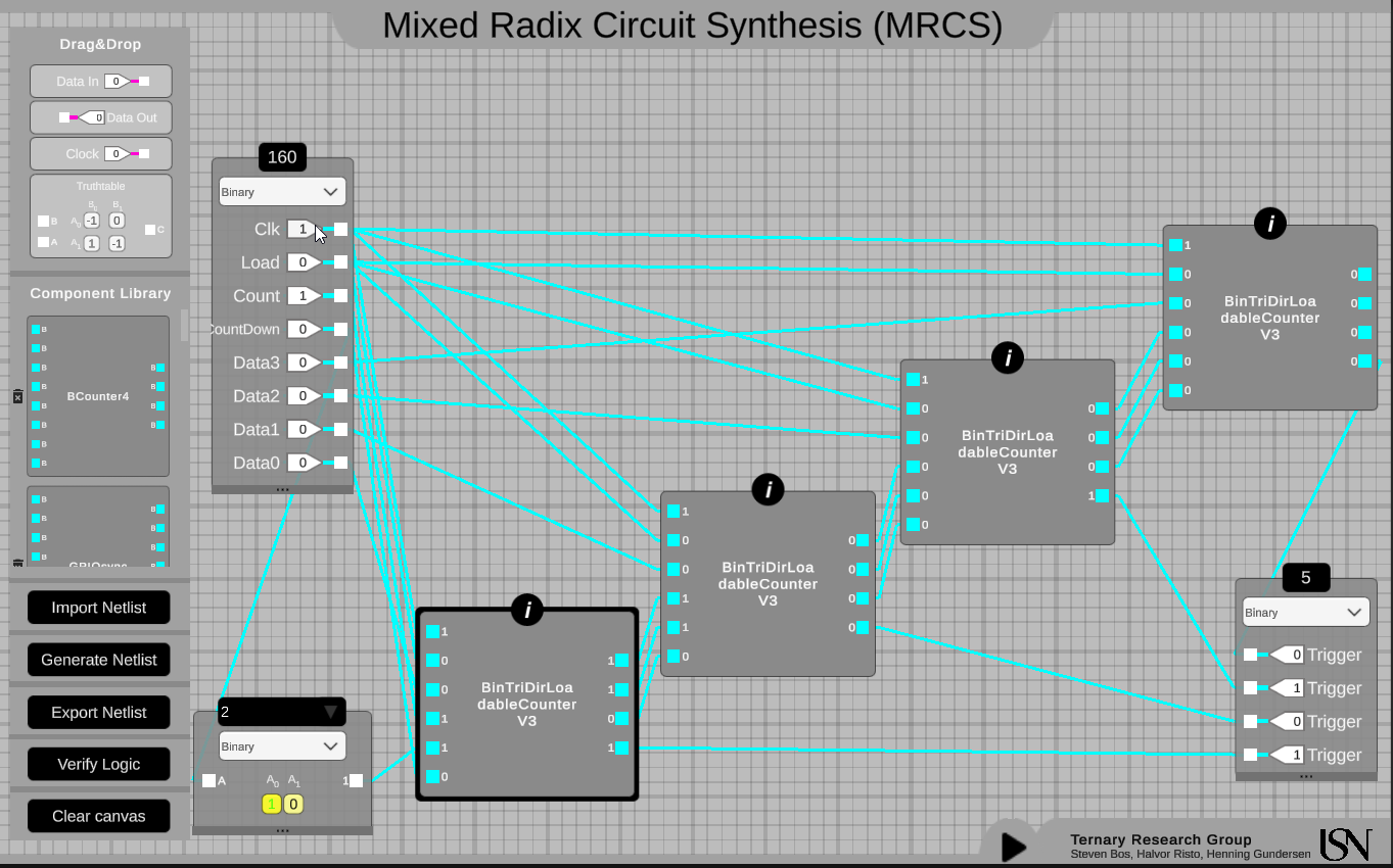
- Description: This chip offers a scalable n-bit counter design that can be used as a program counter by setting the next address (eg. for a JMP instruction). It can work in 3 directions: counting up, down and pause.
- GitHub repository
- Clock: 0 Hz
How it works
See the full documentation, youtube movie and image. Each 1-bit counter has a flip-flop with count logic component reacting synchronously to the rising edge clock pulse and a count logic component that computes and setup the behavior for the next rising edge using async propagation when the level is low.
How to test
The count state is randomly initialized. Typically the first action is to reset the state to zero by setting the load switch and have one clock pulse. The second action is setting the direction by enabling count and setting countDown to true or false (and disable load). The counter overflows to all 0 when all 1 is reached and count up is set.
External hardware
no external hardware needed

IO
| # | Input | Output |
|---|---|---|
| 0 | clock | output3 (bits [0:3]) |
| 1 | count (0 = disable/countPause, 1 = enable) | output2 |
| 2 | load (0 = count mode, 1 = load mode, overwriting any count logic) | output1 |
| 3 | countDown (0 = countUp, 1 = countUp) | output0 |
| 4 | addr3 (bits[4:7] are used for loadable count state) | |
| 5 | addr2 | |
| 6 | addr1 | |
| 7 | addr0 |